Physical Components
The Layout Board
The whole layout is based around a 2500 mm square board hoisted from an I beam on the ceiling (designed to always keep the board level)
This Platform hangs on 4 wires - located at each corner
Later on, an extension was added to the layout, some of which cannot be hoisted due to space - this clips on when the layout is down.
The whole layout was then built up on the main board with three main levels :-
Lowest in the middle,
A half height section with the main 4 platform station at the front
And a higher section at the back with a small 2 platform station, hills and tunnel section
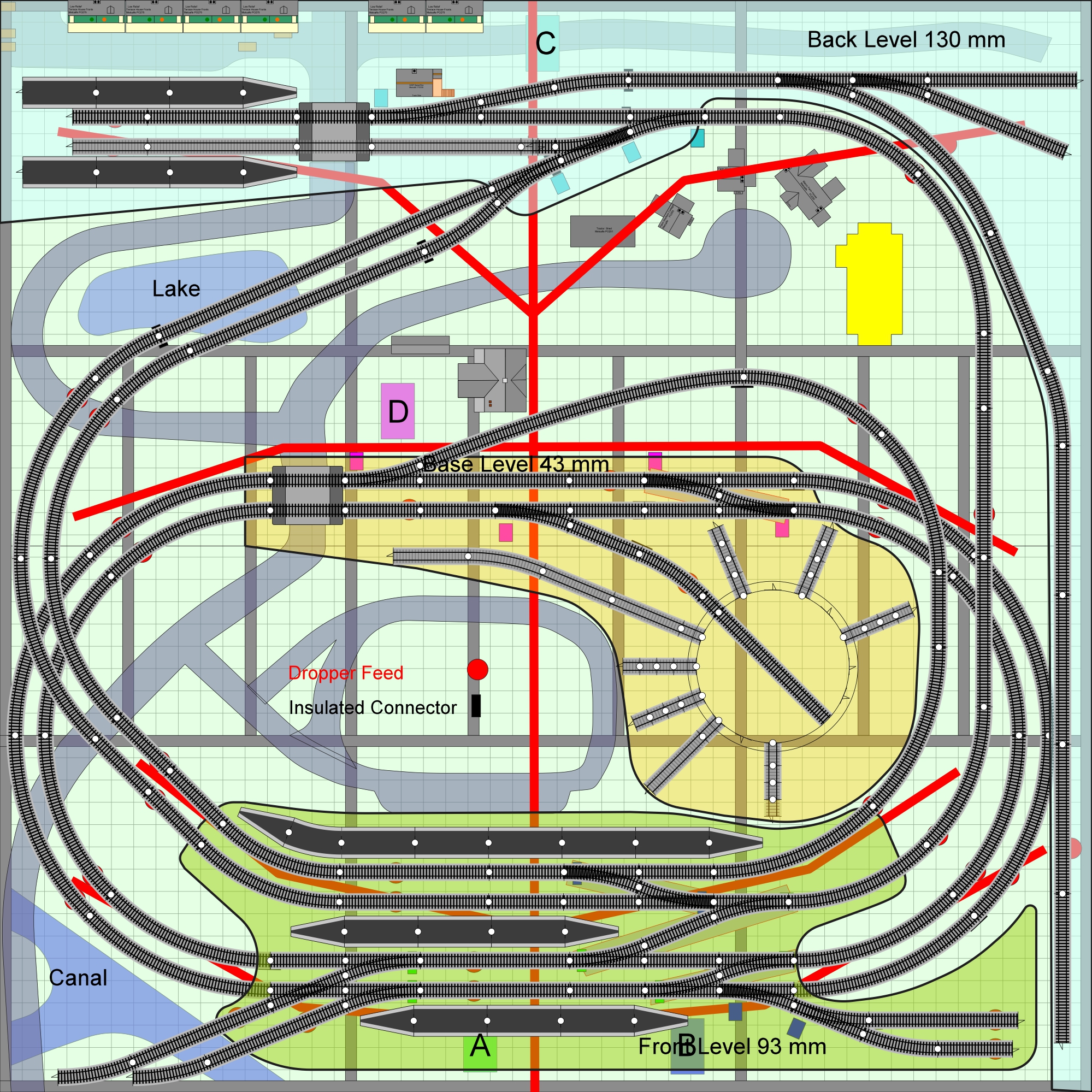
Initial Layout
(Image from Anyrail)
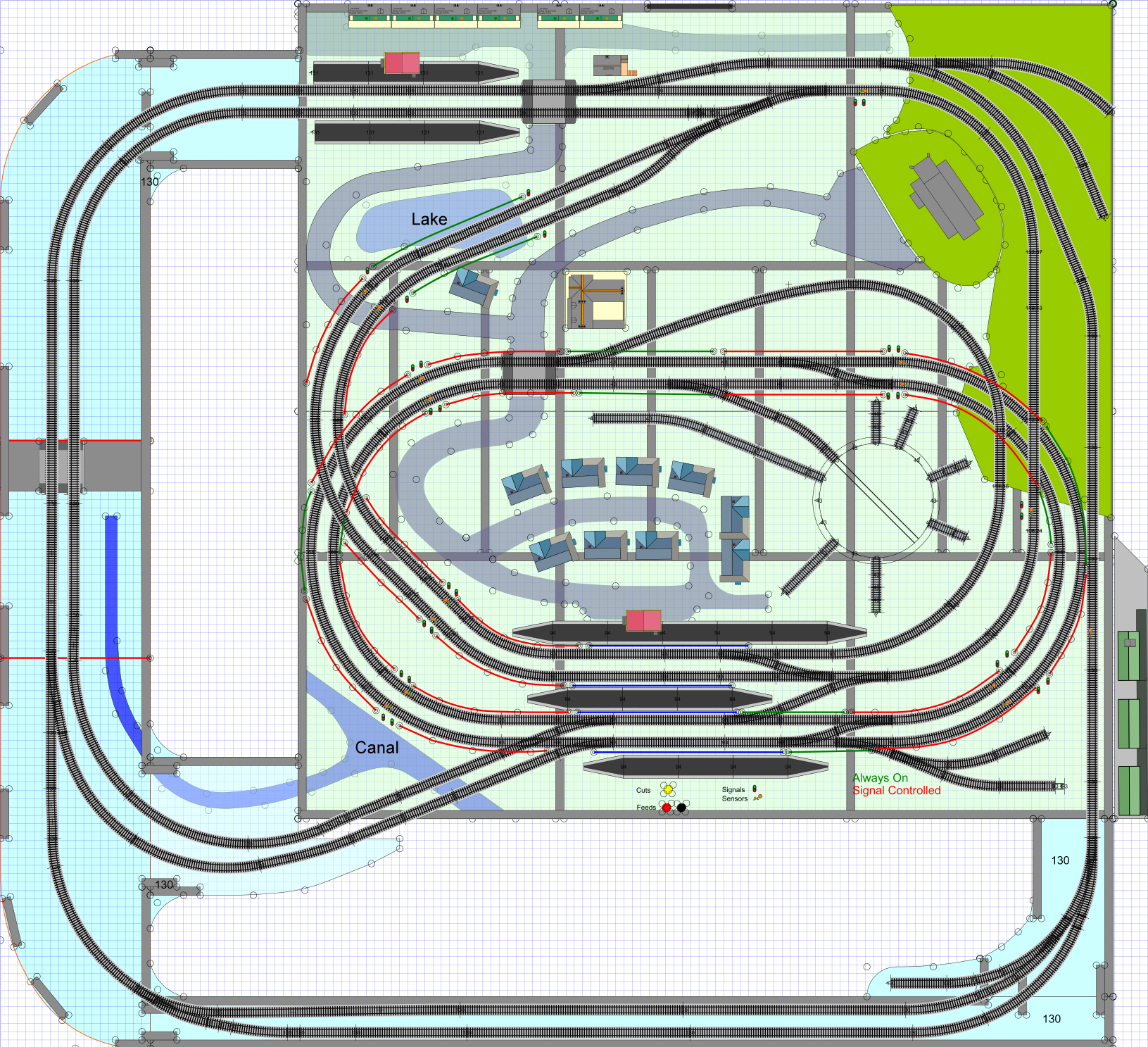
Extended Layout in 2024
In 2024 the layout was extended to make use of the 3 positions where the track allowed exit from the initial square layout
Not all of the extension portion can be hoisted to the ceiling and (as a result) has to be clipped on
The front strip is a long girder bridge and allows us to stand inside this part of the layout
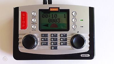
A Hornby Elite Controller mounted on the front of the layout
enabling both manual and computer controlled running of the trains, points etc…
The Railmaster Computer which simply runs Hornby’s Railmaster software.
This software gives us control of train speeds, direction, point control etc… but it is purely a “Time Based” system which enables sequential scripts and loops with NO REAL LOGIC !
The computer is attached to the Hornby Elite controller via USB
Hornby did make a modification to Railmaster in 2019 which allows us to send “External” commands to interface with other software but there is no API and thus no way of pushing input back into Railmaster

Power Supplies
There are a number of power requirements :-
The 15 Volt AC output from the Elite is distributed via a star like wiring frame across the layout
A 12 Volt DC supply is similarly provided across the layout – This 12 Volt Supply is provided by a transformer dedicated to this purpose. This supply is at the back right hand corner of the layout
A Supply to the Powered USB Hub from the adapter supplied with the hub – this is necessary for the sensors and relay board control. The adapter power supply is from the right hand side of the layout alongside the Elite power supply
There is also power to speaker systems etc… including 4 quad speakers (mounted at each corner of the board)
Denkovi Relay Boards
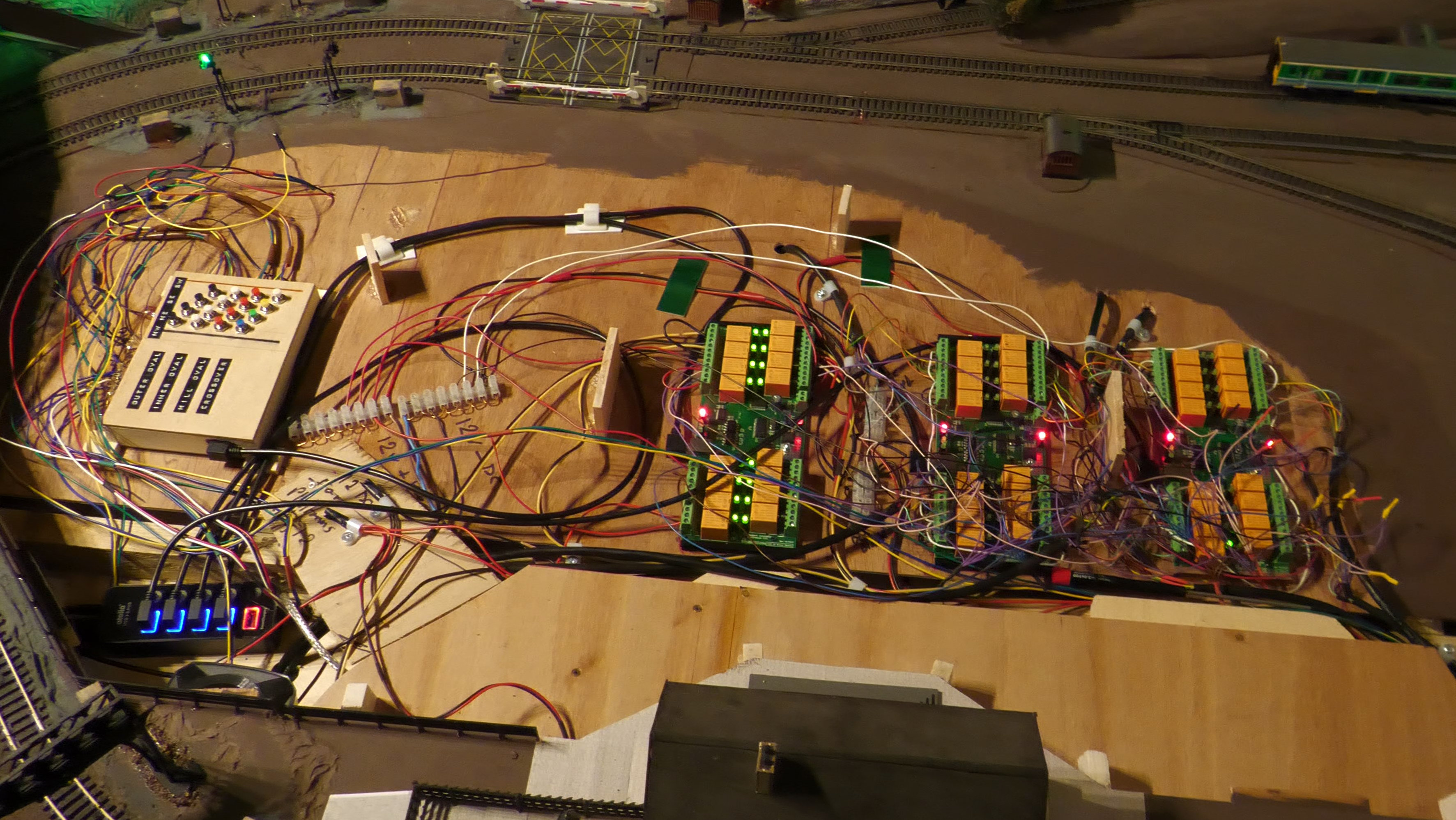
Three USB Electronics Boards mounted centrally on the layout (under the village scene) and One LAN Relay Board mounted at the far left corner (under the terraced houses)
Denkovi USB Controlled Relay Boards
we have three of these boards – they attach to our main computer via USB and each of them has 16 relays that we can switch – they are currently used for track isolation at platforms and for light control
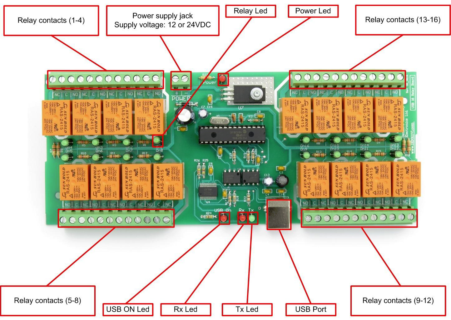
The Relay Boards are mounted on to lower panel underneath the village scene as shown here (the digibee sensor board can also be seen to the left)
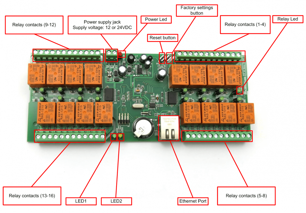
Denkovi LAN Controlled Relay Boards
Note the difference in the relay number allocations - as shown here :-
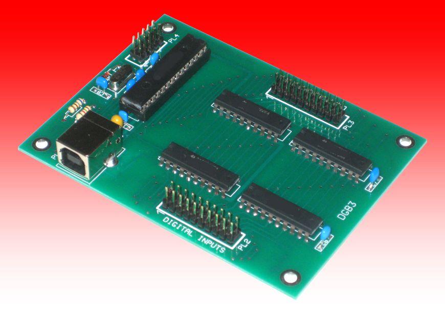
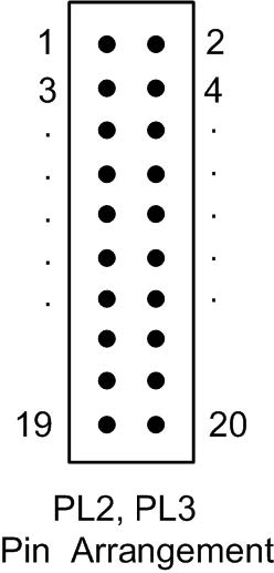
DigiBee+ Sensor Board
This board has 16 inputs that are fed from reed switches around the track – this enables the software to see where trains are, what direction they are travelling and then calculate the speed of trains
 -
-  -
-  -
- 
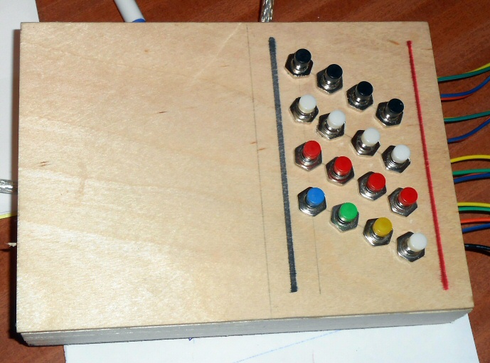
The centre picture above shows the press buttons I included for the DigiBee board - these allow simulation of sensors being activated (for circuit and sensor testing purposes)
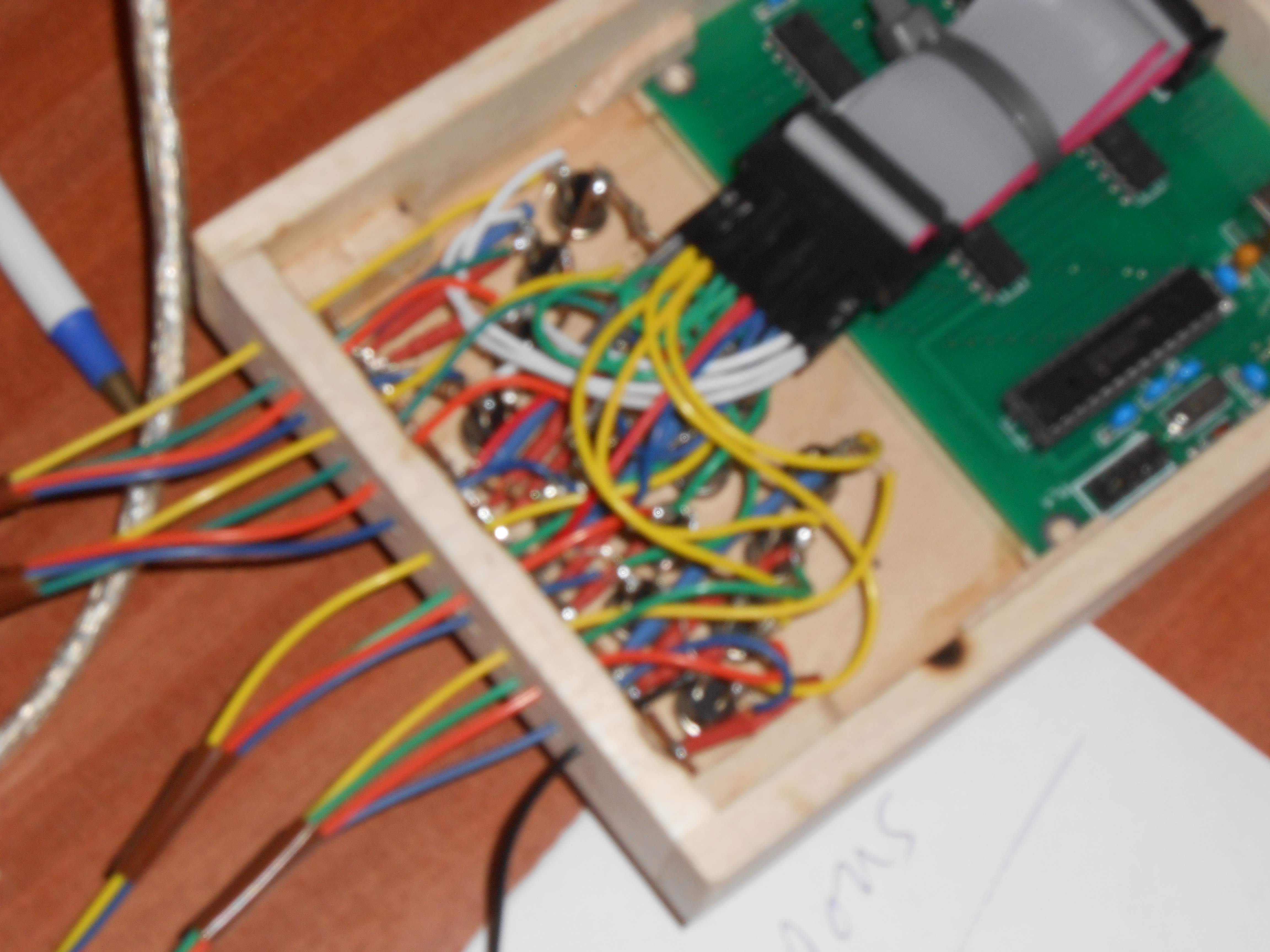
The photo on the right shows the resulting wiring mess !
Note - the board also allows some outputs but, at this time we are only using it for sensing puposes
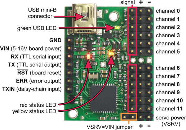
Mini Maestro Servo Board
This board allows us to operate servos (as in radio control models) and therefore create movement on the board - we have not, as yet, made much use of it !