Track Isolation and Signalling


Creation of Short Isolated Portions of Track


The reason for doing this is to achieve accurate stopping of trains – particularly in stations and at red signals


To create a strip in this way we need to either cut the track or fit isolated joiners (plastic)


It does not matter whether we us the Black or Red bus for this purpose – in each case it will be easier to pick a particular rail for cutting


When we isolate a portion of track we end up with 3 entities :-

UNCUT – the uncut rail, ISOLATED – the short piece isolated by the cuts, REMAINDER – the “outside” bits on the cut rail


Table of Isolated Portions of Track


Isolated Rail

Default Direction of Travel

Default Train

Platform 1

Red

Overlap - right to left

n/a

Platform 2

Black

Clockwise - right to left

10 Weathered DMU

Platform 3

Red

Clockwise - right to left

11 Centro DMU

Platform 4

Black

Anticlockwise - left to right

12 Centro DMU


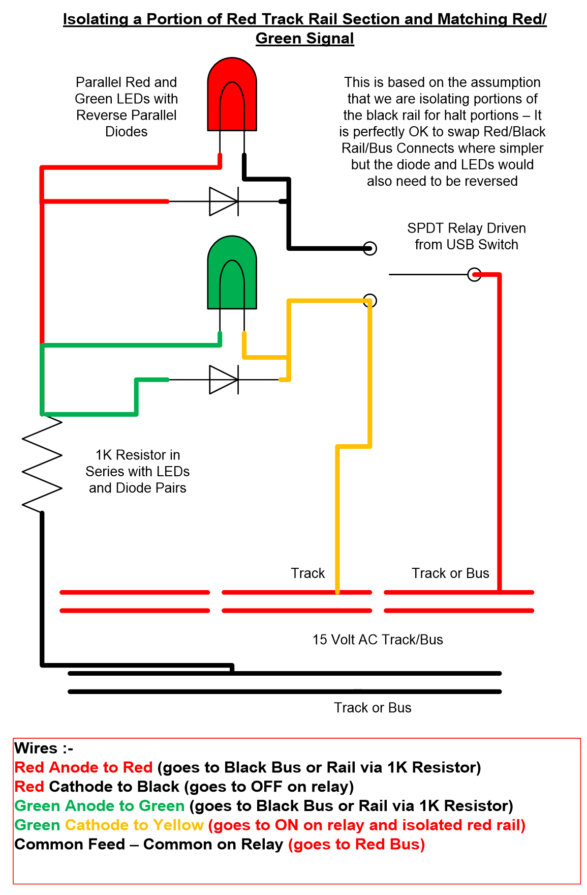
Relays :-

The relay terminals consist of :-

COMMON, ON, OFF


Wiring :-
The connections need to be as follows :-


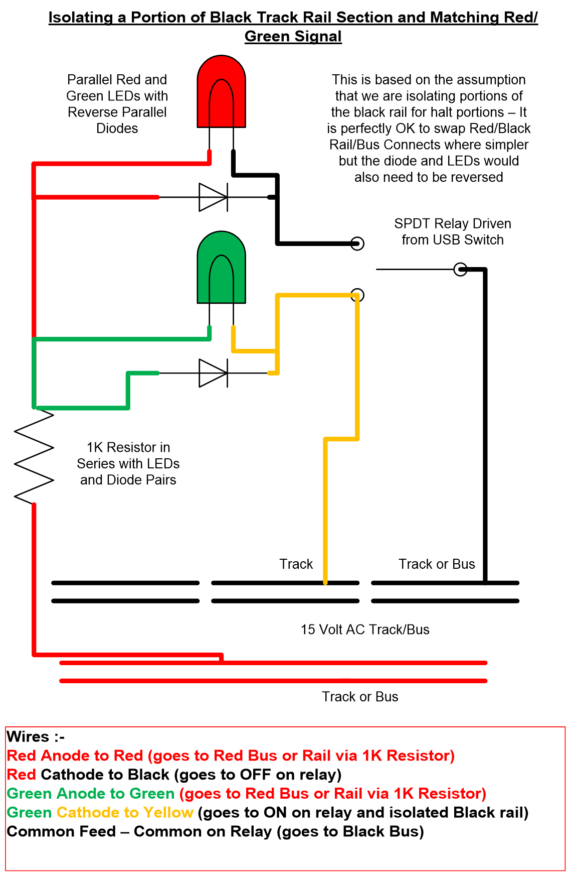
Wire the COMMON terminal on the relay to the REMAINDER (or matching bus)

Wire the ON terminal on the relay to both the isolated portion of track and the red light anode

Wire the OFF terminal on the relay to the green light Anode

Wire the uncut rail (or matching bus) to the common cathode on the lights

The relay will then control both track isolation and the matching lights

Note :- the red/green lights used here must be AC 15v powered with the necessary resistor and diode for the LEDs


-


Controlling Signals


After much analysis of requirements I made the following decisions :-

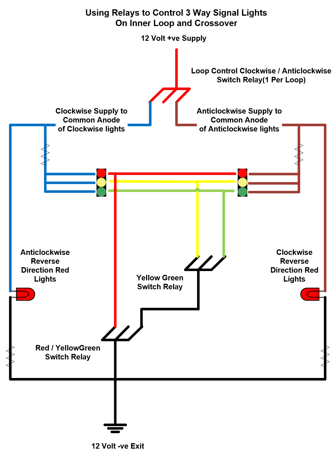
• Signal lights will only be on in one direction on each loop - if the loop is in use for clockwise travel only the clockwise signals will light up (and similarly for the anticlockwise signals)

• One Relay will be used for each loop to activate +ve power for signals etc...

• Two relays are then needed for light control at each position - one for Red or Yellow/Green and one for Yellow or Green (see Relay Board 2 and 3 Configs)

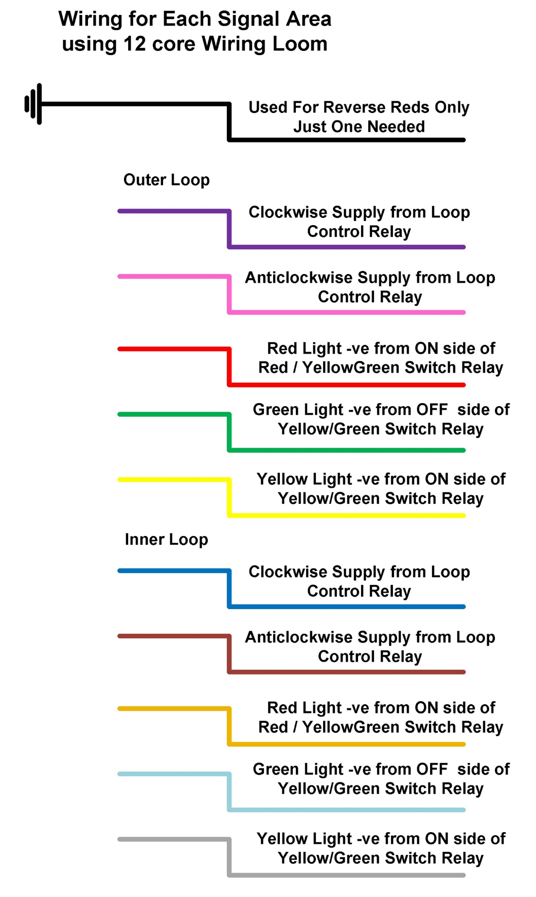
• Using a 12 multicoloured core wire we can then operate each position on a loop from one supply (both clockwise and anticlockwise)


- -


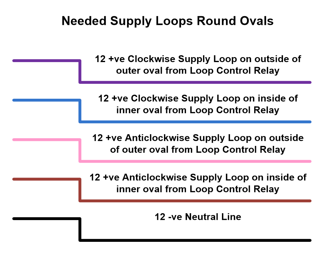
For other purposes such as reverse red lights etc... I have considered putting 5 loops around the underside of the board in line with the tracks

This diagram shows the wires that could be useful


The Next Question – Can we Make Trains Stop at Red Lights ?


When I came to consider this one I very quickly realised that we had already done most of the work to allow the trains to operate in this way

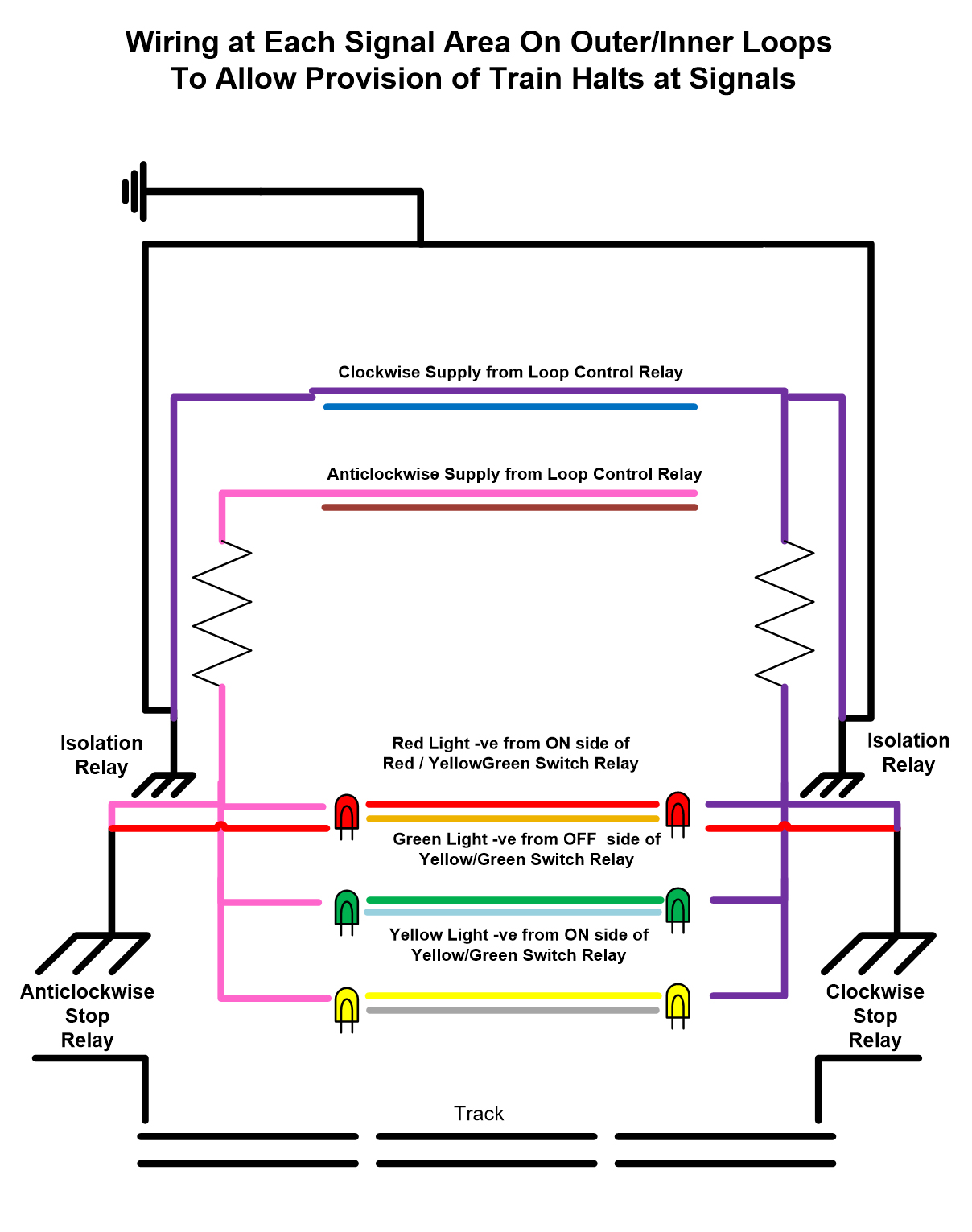
At each signal position we already had a 12v +ve for the train direction and a 12v -ve for the red light – these being the supply for the red light operation

We could, therefore, use a switching relay with the above supply being the switching circuit and the output being a circuit breaker on one rail of the track (on the applicable side of the signal) – we were already isolating portions of track for stations etc...

I understood that the Bachmann DMUs I was operating pick up over the whole bogie length (including the trailer car) which means we will need around 21 inches of isolated track to stop a train successfully

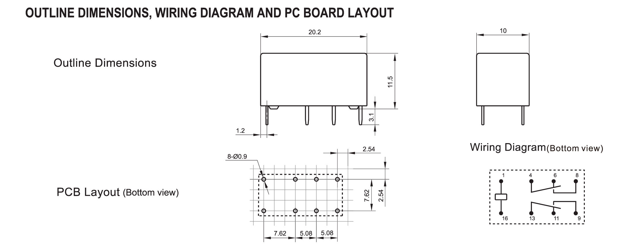
We already had a number of relays – MCB-S-212-CH – which are DPDT 12v switch units so I decided to make use of these (and get some more if ok)

I also 3D printed lineside boxes to hold the relays and hide the wiring

This is the layout of the relay


It may be beneficial to remove unused pins to create more space in the box but pins 1 & 16 are the switching circuit

and either 4/6 or 13/11 can be used to isolate the track as they will be “on” unless the switching circuit is activated meaning that “green” lights are the default scenario


-


A Few Notes about this :-


I initially wired this up without the isolation relay and found myself rather confused because red lights worked as intended but, whenever the signal was switched to green or yellow, both clockwise and anticlockwise direction lights came on.

After much tracing of the circuit (and proving that it was the control wires to the stop relays that were making the difference)

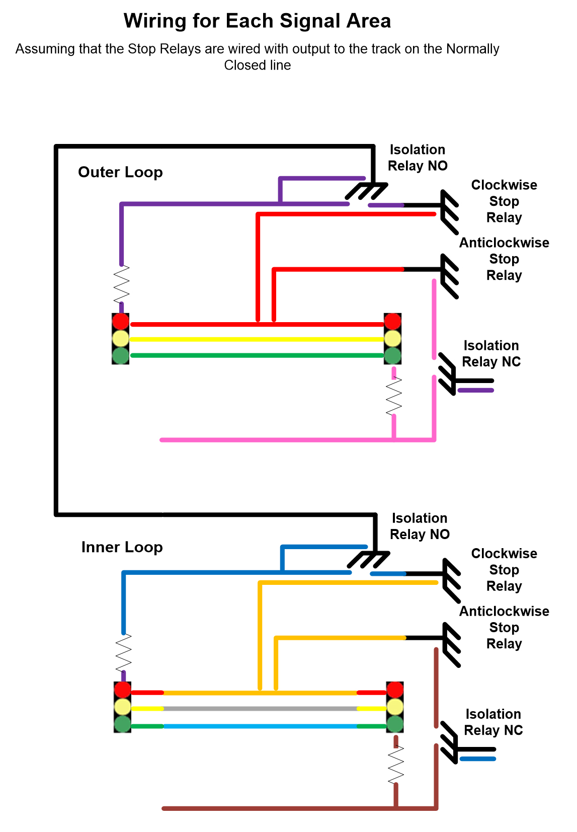
I then decided it needed an isolation relay (one DPDT as above should suffice)


This relay is wired up as follows :-

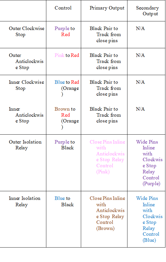
• Control is from the Clockwise supply +ve and the universal Black -ve

• The control to the clockwise stop relay is wired across the close pins - either 4/8 or 13/9

• The control to the anticlockwise stop relay is wired across the wide pins - either 4/6 or 13/11


This provides total isolation between clockwise and anticlockwise lights


So – for a complete signal set we needed these DPDT relays wiring up


I also had to consider the length to use for “Track Isolation”

The DMUs in use at the time had electric pickup on all 4 bogies which was a length of 21 inches.

To isolate this length of track every time meant there was very little space to spare in some locations

I therefore made the decision to remove the pickup from the rear bogies of the trailing car thus giving a pickup length of under 15 inches which was far easier to work with on the layout